And just when I thought I was done with converting old images into BMP format … another picture format attracted my curiosity.
For fun, read my previous post about decoding old-school SCR Images
Background
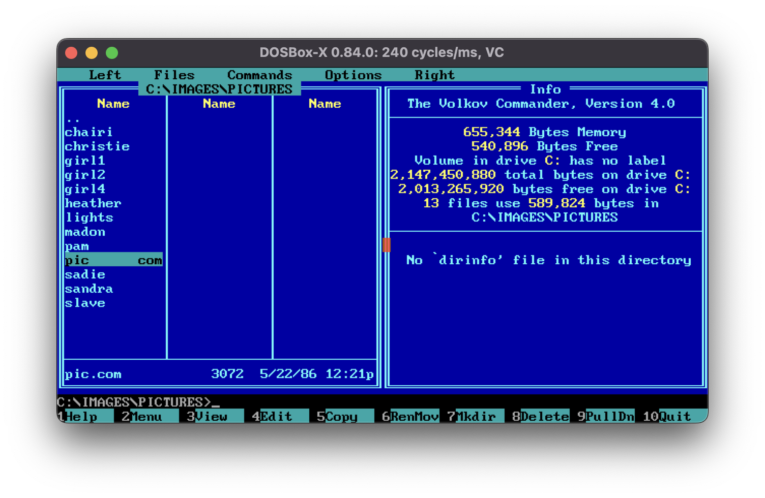
Looks like I have found a program that was used to print posters (maybe?). This program came with number of images in the package:
 When ran,
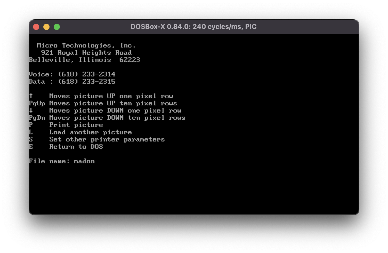
 PIC.COM shows the following screen. We can type the file name we want to open:
 And, when opening the
 MADON file, we see a “Madonna” poster:
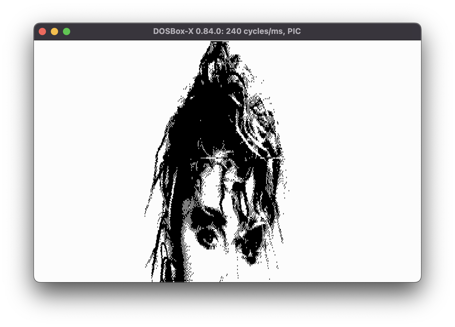 Using the arrow keys we can scroll the view up and get more details of the poster. Which means the image is larger than the actual view port.
The program also seems to use 640x200 resolution. As a reminder, this resolution sports a whopping 1 bpp with only black and white colors.
The file structure
Following the existing procedure, let’s see what the file format is. To achieve that we need to see its hex view:
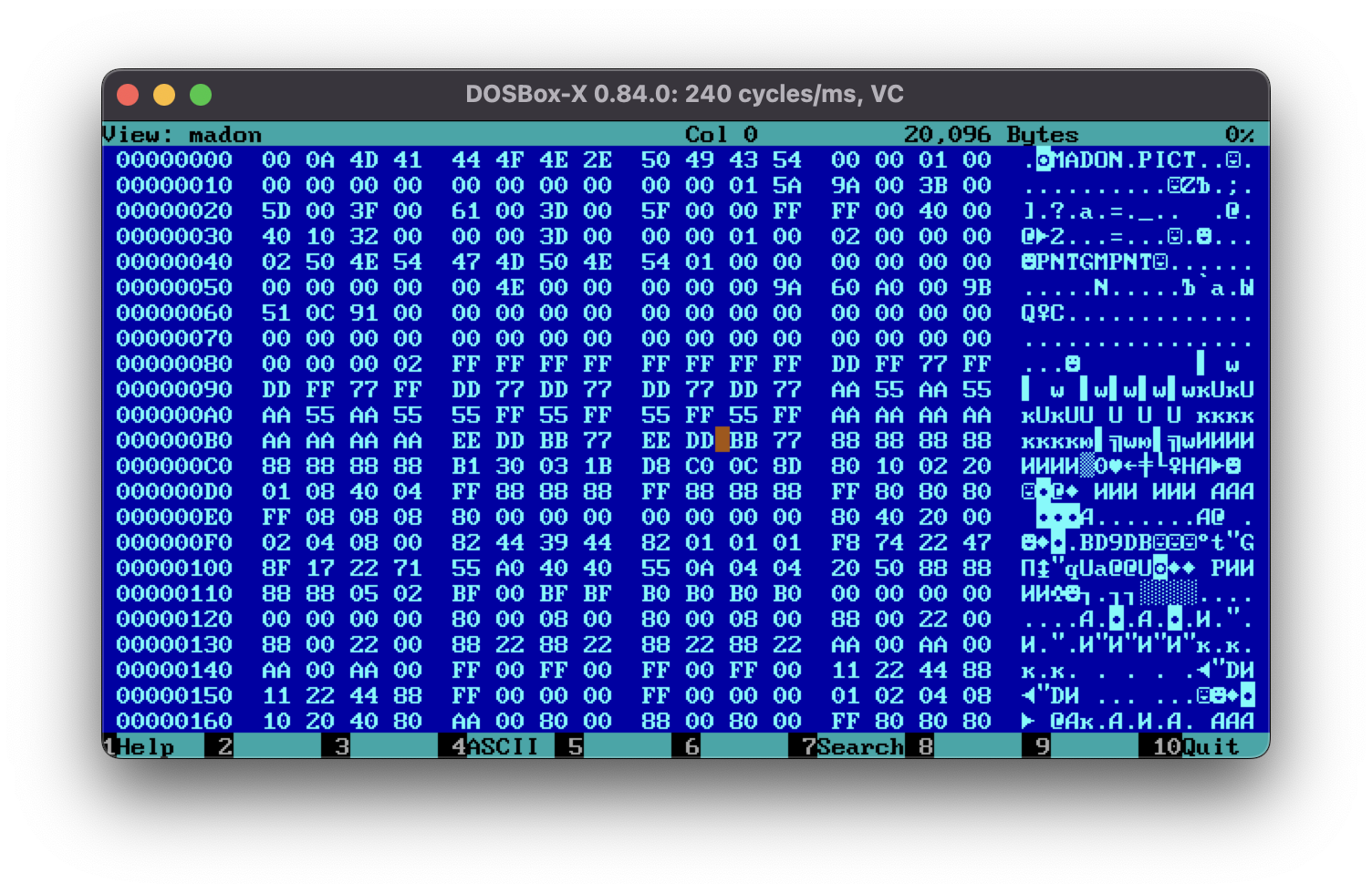 Hm, interesting. This file seems to actually have a header. That might make the decoding a bit more complicated as this means that the header might contain image data size or any other meta information required to decode it. Also the file sizes are all different which, can point to a compression format.
Reversing the executable
To be honest I have no idea how to approach this format and I the most reasonable way of proceeding would be to study the source code of the PIC.COM utility.
To achieve that, I have the amazing DOS program called Sourcer which I found lying around my DOS-era archives:
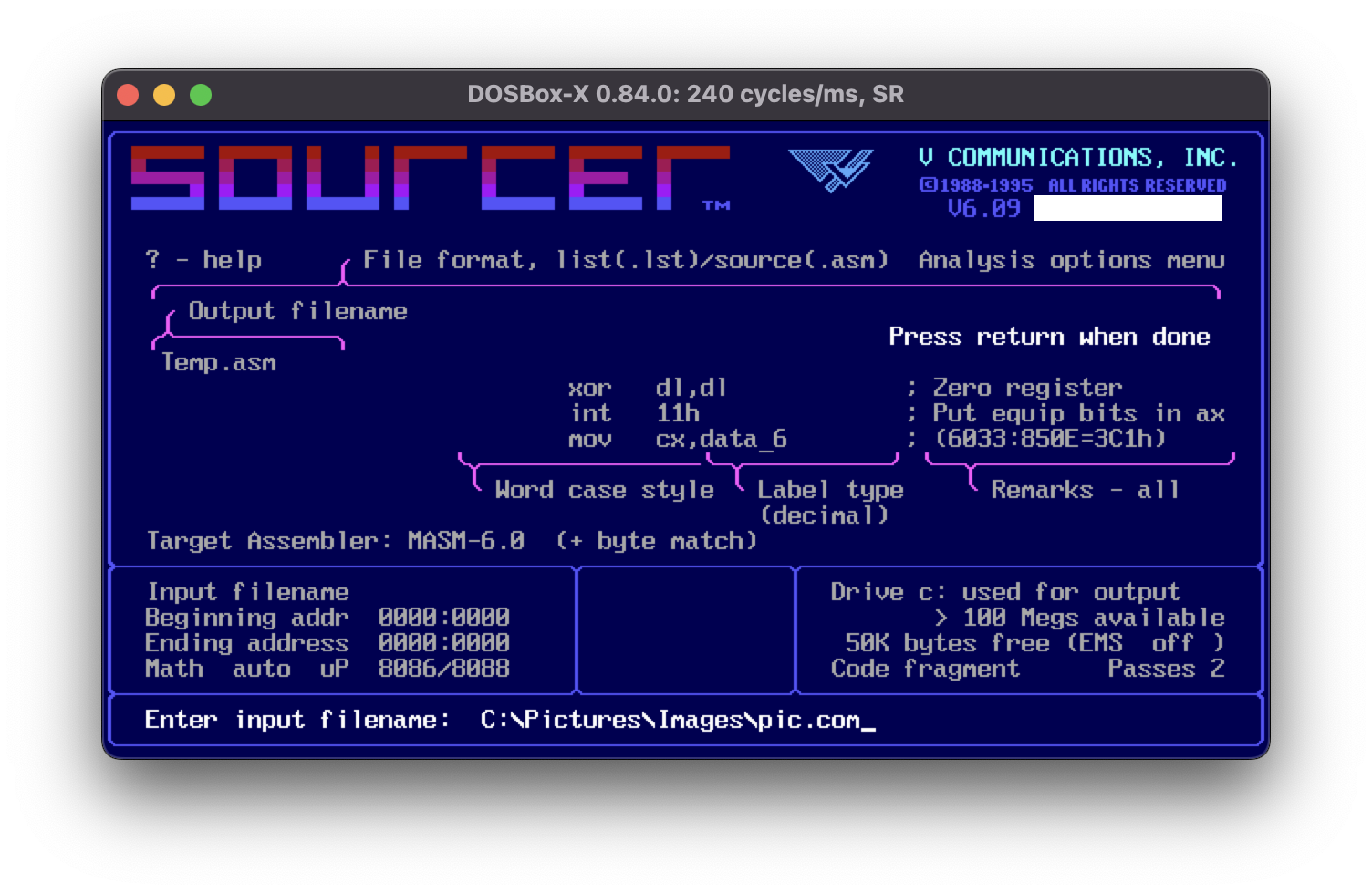
In the above screenshot, we select the output format of the dec-compiled source as MASM-compatible assembly language and select the input file.
As side note, check out the cool UX that this program sports. I just love it!
The output of running Sourcer is a nice PIC.ASM file that has been annotated and ready to be looked at. Here is a small snippet:
;��������������������������������������������������������������������������
;
;                       External Entry Point
;
;��������������������������������������������������������������������������

real_start:
		push	ax
		push	bx
		push	cx
		push	dx
		push	si
		push	di
		push	ds
		push	es
		push	cs
		pop	ds
		call	sub_11
		lea	bx,cs:[0BE3h]			; Load effective addr
		mov	cs:image_buffer_ptr,bx
loc_1:
		mov	ax,3
		int	10h				; Video display   ah=functn 00h
							;  set display mode in al
		mov	ax,600h
		mov	bh,7
		mov	cx,0
		mov	dx,184Fh
		int	10h				; Video display   ah=functn 06h
							;  scroll up, al=lines
							;   bh=attrib, cx+dx=window size
		lea	dx,data_8			; ('') Load effective addr
		mov	ah,9
		int	21h				; DOS Services  ah=function 09h
							;  display char string at ds:dx
		lea	dx,data_15			; Load effective addr
		mov	ah,0Ah
		int	21h				; DOS Services  ah=function 0Ah
							;  get keybd line, put at ds:dx
		mov	al,cs:data_16
		mov	ah,0
		mov	si,ax
		mov	cs:data_17[si],0
		mov	byte ptr cs:data_14[si],24h	; '$'
		mov	cx,si
		mov	si,zero
The rendering process
Note how Sourcer has named the memory locations using data_xx names. That’s to be expected since we do not have debug symbols and the de-compiler simply attributed random names to each memory location and sub-routine.
This means that the only way to understand the actual code is to look at it, and replace these auto-generated names with the actual names as we go along.
My process is simple. when I understand the purpose of a memory location/variable/sub-routine, I simply replace that name with something more readable based on its purpose.
But, first things first, where is the sub-routine that draws on the screen? The way to approach that is to find the code that references the CGA video memory segment 0xb800. Searching the file we immediately find the following sub-routine:
sub_7		proc	near
		push	ax
		push	bx
		push	cx
		push	dx
		push	si
		push	di
		push	bp
		push	es
		mov	ax,0B800h   		; <------ CGA VIDEO MEMORY REFERENCE
		mov	es,ax
		mov	bp,data_51e
		mov	ax,cs:data_38
		mov	si,48h
		mul	si			; dx:ax = reg * ax
		add	ax,cs:data_37
		mov	bx,ax
		mov	cx,64h

locloop_57:
		push	cx
		mov	si,data_1e
		mov	di,data_51e
		mov	cx,48h

locloop_58:
		mov	al,[bx+si]
		xor	al,0FFh
		mov	es:[bp+di],al
		inc	si
		inc	di
		loop	locloop_58		; Loop if cx > 0

		add	bx,data_7e
		add	bp,50h
		pop	cx
		loop	locloop_57		; Loop if cx > 0

		mov	bp,data_52e
		mov	ax,cs:data_38
		mov	si,48h
		mul	si			; dx:ax = reg * ax
		add	ax,cs:data_37
		mov	bx,ax
		add	bx,48h
		mov	cx,64h

locloop_59:
		push	cx
		mov	si,data_1e
		mov	di,data_51e
		mov	cx,48h

locloop_60:
		mov	al,[bx+si]
		xor	al,0FFh
		mov	es:[bp+di],al
		inc	si
		inc	di
		loop	locloop_60		; Loop if cx > 0

		add	bx,90h
		add	bp,50h
		pop	cx
		loop	locloop_59		; Loop if cx > 0

		pop	es
		pop	bp
		pop	di
		pop	si
		pop	dx
		pop	cx
		pop	bx
		pop	ax
		retn
sub_7		endp
We can separate this sub-routine into two parts:
- From the
mov ax,0B800htoloop locloop_57, the code draws the picture into the first page of the CGA video memory, - And from
mov bp,data_52etoloop locloop_59, the second page. The value ofdata_52eis0x2000.
For each page it looks as there are two loops. I won’t try to go through each line of the assembly, though as there’s too much to follow. Instead, here’s the pseudo-C code of this function:
int video_memory = 0xb800 // first memory page at 0xb800
for (row = 0; row < 200; row += 2) {
    for (col = 0; col < 72; col++) {
		int pix8 = image_bytes[scroll_index + (row * 80) + col] ^ 0xff
        video_memory[row * 80 + col] = pix8
    }
}

video_memory = video_memory + 0x2000 // next memory page
for (row = 1; row < 200; row += 2) {
    for (col = 0; col < 72; col++) {
		int pix8 = image_bytes[scroll_index + (row * 80) + col] ^ 0xff
        video_memory[row * 80 + col] = pix8
    }
}
Right, so what’s with all these magic numbers: 72 (0x48), 200 (0x64 * 2), 80 (0x50) and why are we XOR-ing with 0xff? Remember that each row is 640 pixels? That translates to 640 pixels / 8 ppb = 80 bytes. But why are we only copying 72 bytes into the video memory? Well that’s up to the original developer; apparently the width of these images is 72 bytes * 8 bpp = 576 pixels. The height of the same video mode is 200 pixels which explains the loops.
The file format
Since we have identified the rendering function, now we need to figure out what is the actual file format. In the previous section, the memory at data_37 is the actual raw image bytes which are being copied into the video memory. The data_38 is the vertical offset in the image to copy into the video memory (remember, one can scroll up and down using arrow keys).
Looking further into the source code there’s a few sub-routines that stand out:
sub_9		proc	near
		push	dx
		lea	dx,data_17		; Load effective addr
		mov	ax,3D00h
		int	21h			; DOS Services  ah=function 3Dh
						;  open file, al=mode,name@ds:dx
		mov	cs:data_18,ax
		pop	dx
		retn
sub_9		endp
This one seems to open the input file and store the handle into data_18 memory location. Following that variable we find:
sub_10		proc	near
		push	bx
		push	cx
		push	dx
		mov	ah,3Fh			; '?'
		lea	dx,data_19		; Load effective addr
		mov	cx,80h
		mov	bx,cs:data_18
		int	21h			; DOS Services  ah=function 3Fh
						;  read file, bx=file handle
						;   cx=bytes to ds:dx buffer
		mov	cs:data_35,0
		pop	dx
		pop	cx
		pop	bx
		retn
sub_10		endp
This one seems to read 128 (0x80) bytes from the input file into data_19 memory location; and resets another memory location at data_35 to 0. Let’s follow the thread further:
sub_8		proc	near
		push	si
		mov	si,cs:data_35
		cmp	si,80h
		jl	loc_61			; Jump if <
		call	sub_10
		mov	si,data_1e
loc_61:
		mov	al,cs:data_19[si]
		inc	cs:data_35
		pop	si
		retn
sub_8		endp
Alright, here they seem to be returning a byte from the buffer filled in by sub_10. If the read byte exceeds 128 (0x80), this sub-routine calls the aforementioned sub_10 to load more bytes. This explains why data_35 is set to zero in sub_10. It’s basically an index into the buffer which needs to be refilled at each 128 bytes.
It makes sense to find the uses of sub_8 and sub_10. The following code is found at some point when the name of the file is entered by the user:
		lea	dx,data_12	; ('') Load effective addr
		mov	ah,9
		int	21h		; DOS Services  ah=function 09h
					;  display char string at ds:dx
		call	sub_9
		jnc	loc_3		; Jump if carry=0
		lea	dx,data_13	; ('') Load effective addr
		mov	ah,9
		int	21h		; DOS Services  ah=function 09h
					;  display char string at ds:dx
		jmp	loc_25
loc_3:
		call	sub_2
		mov	cx,5

locloop_4:
		call	sub_10
		loop	locloop_4	; Loop if cx > 0
This code calls sub_9 which opens the file and stores the handle, then, it calls sub_2 and then, calls sub_10 5 times in a loop. sub_2 seems to simply clean up the memory location where the image contents will be loaded and sub_10 called 5 time will basically skip the first 4 * 128 = 512 bytes. Looking at the hex view again, it seems that it might correspond to the header part of the file:
This seems to indicate that PIC.COM simply ignores the header!
The following piece of code finally reveals the last piece of the puzzle (cleaned for clarity):
		mov	cs:data_35,80h
		mov	cx,2D0h
		mov	bx,cs:data_37

locloop_5:
		mov	si,0
		mov	cs:data_34,0
		push	cx
loc_6:
		call	sub_8
		cmp	al,0
		jl	loc_8			; Jump if <
		mov	ah,0
		mov	cx,ax
		inc	cx

locloop_7:
		inc	cs:data_34
		call	sub_8
		mov	[bx+si],al
		inc	si
		loop	locloop_7		; Loop if cx > 0

		jmp	short loc_10
		db	90h
loc_8:
		mov	cl,al
		mov	ch,0
		mov	ax,100h
		sub	ax,cx
		mov	cx,ax
		inc	cx
		call	sub_8

locloop_9:
		inc	cs:data_34
		mov	[bx+si],al
		inc	si
		loop	locloop_9		; Loop if cx > 0

loc_10:
		mov	ax,cs:data_34
		cmp	ax,48h
		jl	loc_6			; Jump if <
		pop	cx
		add	bx,48h
		loop	locloop_5		; Loop if cx > 0
The pseudo-C version of this code is:
for (int row = 0; row < 720; row++) {
	int col = 0;

	while (col < 72) {
		int count = read_next_image_byte()
		if (count < 0) {
			// if count is negative, transform to positive and assume the next
			// byte repeats these many time plus one.
			count = -count
			int value = read_next_image_byte()
			while (count >= 0) {
				image_bytes[row * 72 + col] = value
				col++
			}
		} else {
			// if the count is positive, read said amount of following bytes plus one from the file.
			while (count >= 0) {
				image_bytes[row * 72 + col] = read_next_image_byte()
				col++
			}
		}
	}
}
Oh well, look at that. Another RLE decoder. Seems to decode each row of 72 bytes individually and assumes that there are always 720 rows.
Show me the code!
Alright, enough research, let’s write that python code again. I have actually reused much of the existing code used in the previous decoding attempt so this one will be easier to carry out.
First, the *RLE decoder:
def _expand_comp_rle(input: bytes, start: int, row_len: int) -> bytearray:
    i=start

    output=bytearray()
    row=bytearray()

    while i <len(input):
        if len(row) >= row_len:
            output.extend(row)
            row.clear()

        cmd=input[i]

        repeats=(cmd & 0x80) == 0x80
        if repeats:
            count=0x100-cmd
        else:
            count=cmd

        count +=1
        i+=1

        if repeats:
            if i == len(input):
                _logger.warning(f"Encountered a repeat command for {count} at {hex(i - 1)} at EOF. Assuming 0x00.")
                rep=0
            else:
                rep=input[i]
            row.extend([rep]*count)
            i+=1
        else:
            row.extend(input[i:i+count])
            i+=count

    if len(row):
        output.extend(row)

    return output
This is the same code as the pseudo-C above. The start and row_len are used to control the decoding part (maybe will use in the future). The count=0x100-cmd line is equivalent to count=-count.
Now, the code that actually pulls things together follows as:
def _process_pic(raw: bytes, width: int, height: int, bpp: int, palette: dict[int, int]) -> np.ndarray:
    pages=(bytearray(), bytearray())

    HEADER=0x80*5
    ROWS=720
    COLS=72

    raw=_expand_comp_rle(raw, HEADER, COLS)
    for row in range(ROWS):
        page=pages[row%2]

        for col in range(COLS):
            byte_index=row*COLS+col
            if byte_index >= len(raw):
                break

            col_byte=raw[byte_index]^0xff

            page.append(col_byte)

    _pad_buffer(pages[0], 0x2000)
    _pad_buffer(pages[1], 0x2000)

	mode=CGA_modes['CGA6']
    return _render(pages, COLS * 8, ROWS, mode['bpp'], mode['palette'])
And, finally, just in the previous blog post, we can simply export the 2D ndarray to a bitmap:

Disclaimer
It actually took me a good few hours while on a long cross-Atlantic flight to figure out the
PIC.COMcode and reinterpret it as python code.
Hope you enjoyed the post, Cheerios!